Assembly
I decided to somewhat redesign the initial design I created in Fusion 360. This decision was partly because I wanted to try out Onshape, which is another cloud-based CAD program, but also because I wasn't really satisfied with the look of the original design. You can find the most up to date version here.
Design
The three-part sandwich structure remains, but I opted for components that would be easily 3D printable. The top and bottom parts will have M3x5x4 threaded inserts to which the middle part connects with M3x6 bolts. The bottom part has a hole for wires; in this case, we need a 5V power supply for the ESP, the motors and the sensors.
The middle part houses the slip ring and serves no other function.
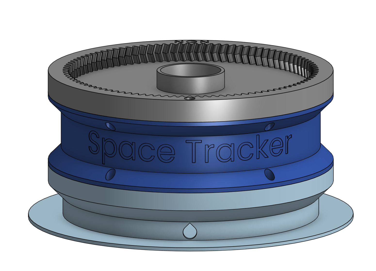
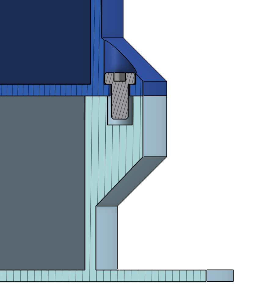
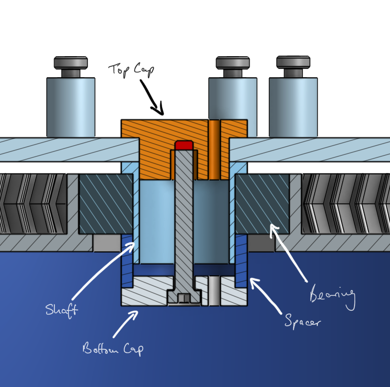
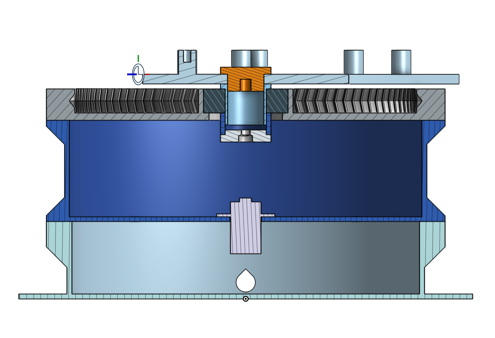
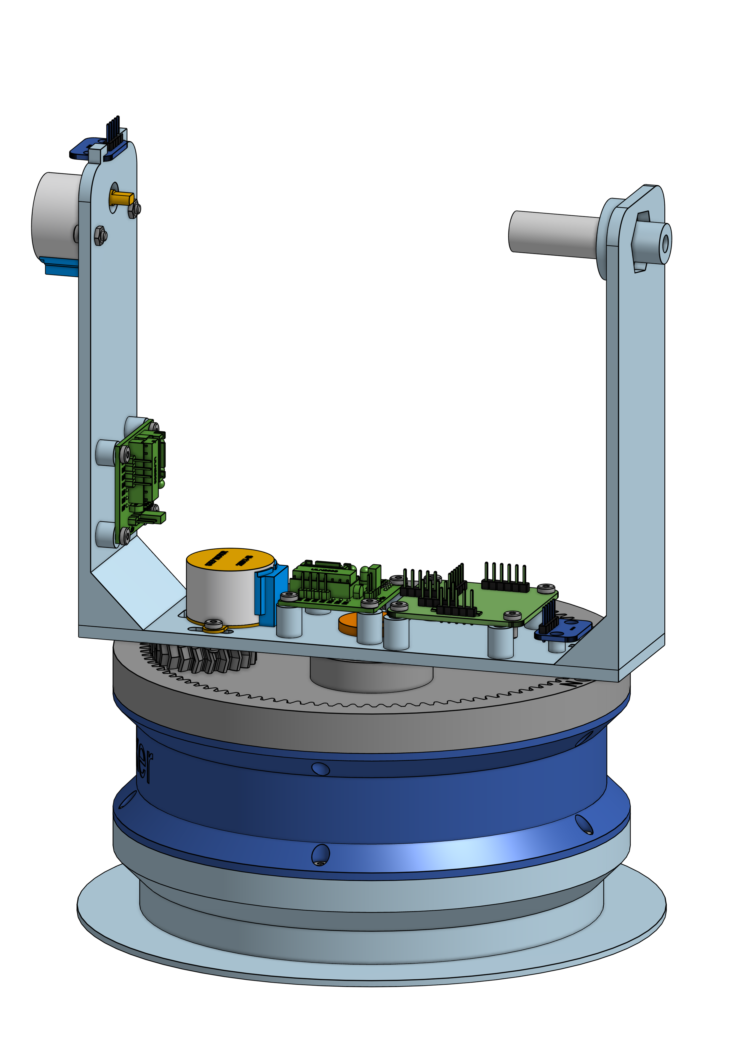
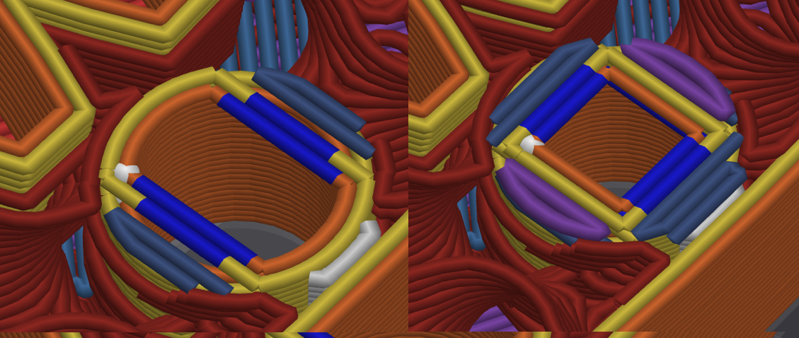
The interesting part comes when we get to the top part of the base. It is still an internal gear with a bearing in the middle. I went with double helical/herringbone gears, because I think they look cooler, there isn't any pratical reason to it. The bearing will press-fit into a mount. To connect the moving bracket to the top part, we will use a structure that consists of four 3D printed parts and one bolt with a threaded insert. There's one shaft that goes into the bearing, then the bracket goes on top of that and will be sandwiched between two caps and a spacer, which are pulled together with the bolt and threaded insert. There's also a little slot in both caps to allow the cables from the slip ring to pass through. Additionally, there are two inserts for magnets on the opposite sides of the top part, so we can determine the position of the bracket with the hall effect sensors.
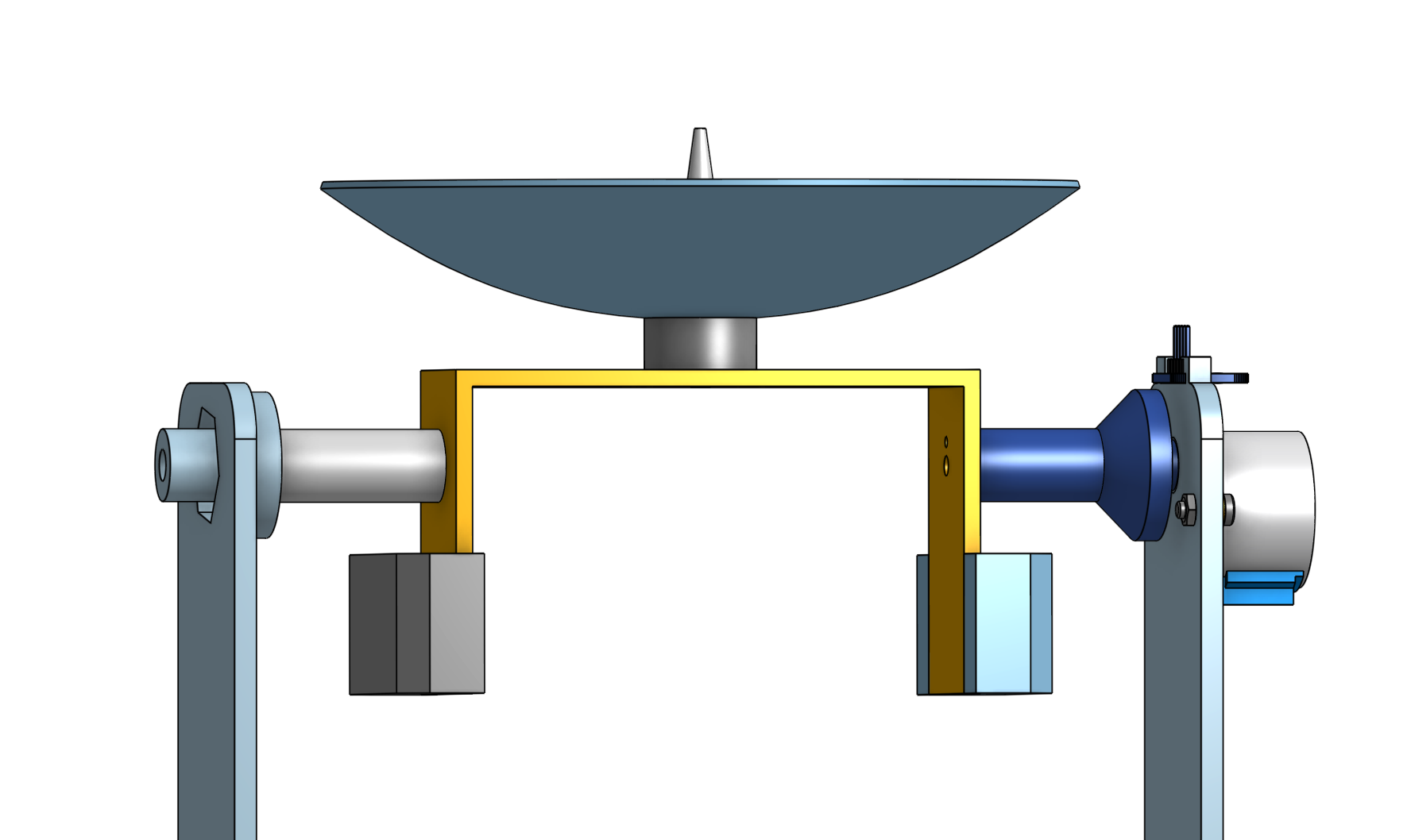
The bracket itself consists of three parts that will be screwed together with bolts and threaded inserts. There are various standoffs on the bracket for the boards and cutouts to mount the motors.
The satellite dish is fixed to an axle that press-fits onto the stepper motor, with another axle extending through an additional bearing.
Supportless holes
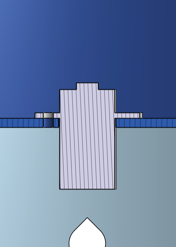
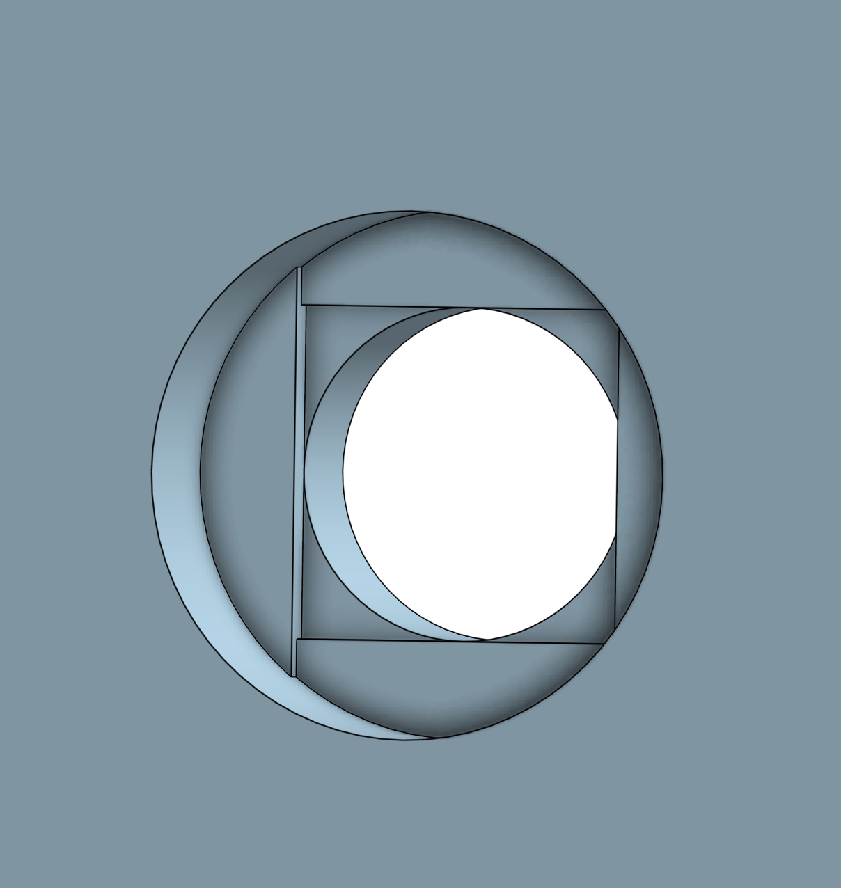
Due to the design, some of the holes/bores must be printed in mid-air, which can cause issues. This is because the printer will attempt to print a circular perimeter into the air, which, of course, won't work.
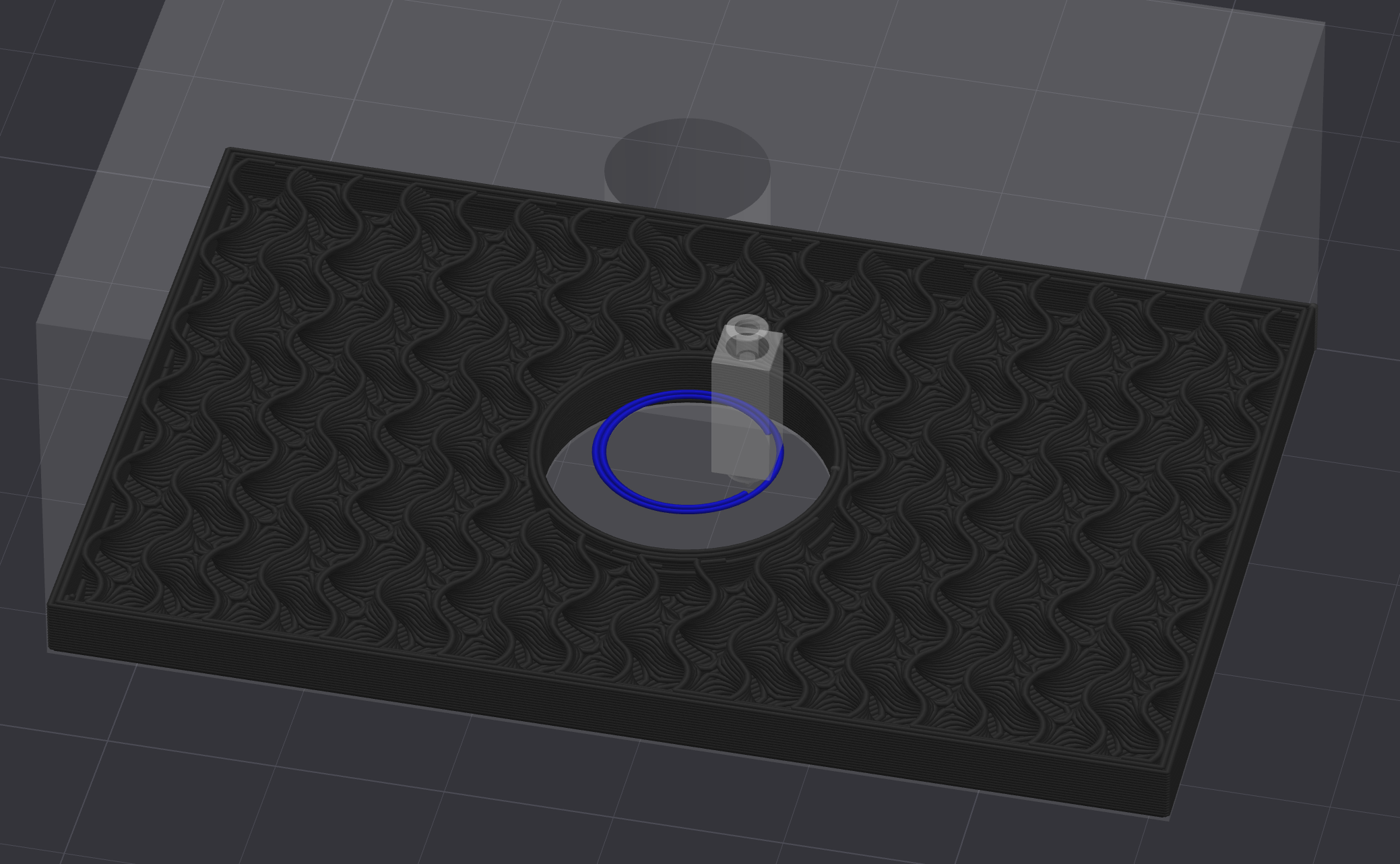
Here's where I used a little trick to make these holes printable. If you use two rectangles that have their sides tangent to the inner circle (one horizontal and one vertical), you can extrude them both slightly deeper than the depth of the blind hole. This results in the printer creating a bridge over the hole, which is a much more manageable task.
3D Printing
The parts were all printed on a Bambu Lab P1S using PETG material. I opted for a layer height of 0.2 mm, with 2 walls, and a 15% infill density. This setup is more than sufficient since there aren't really any parts that will experience significant stress. I printed a few test parts for critical areas first to make sure that everything fits as expected.
Assembling
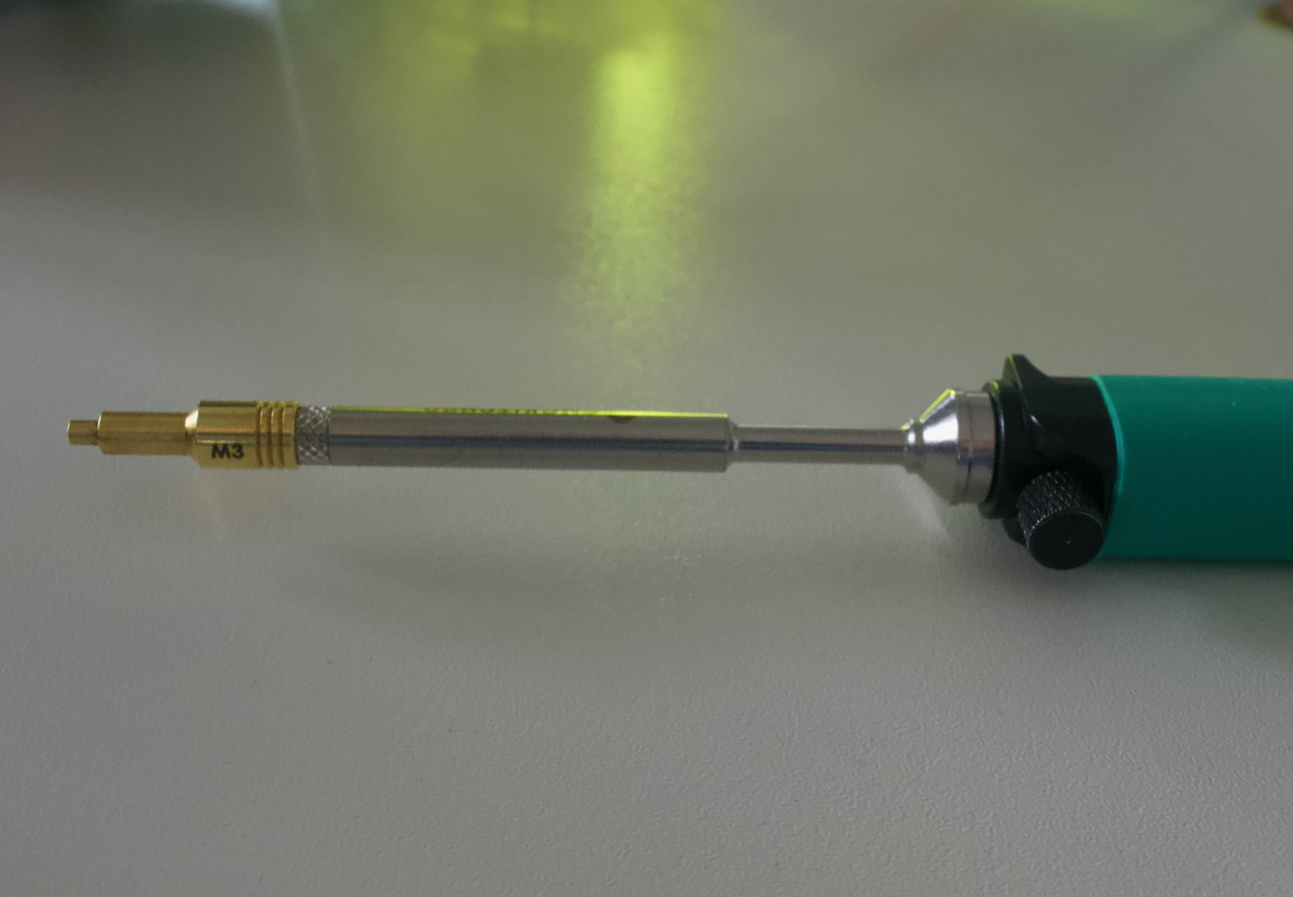
For the installation of the threaded inserts, I used a specialized soldering iron tip designed for this purpose. The tip features a threaded end onto which you can attach variously sized tips to accommodate different sizes of threaded inserts.
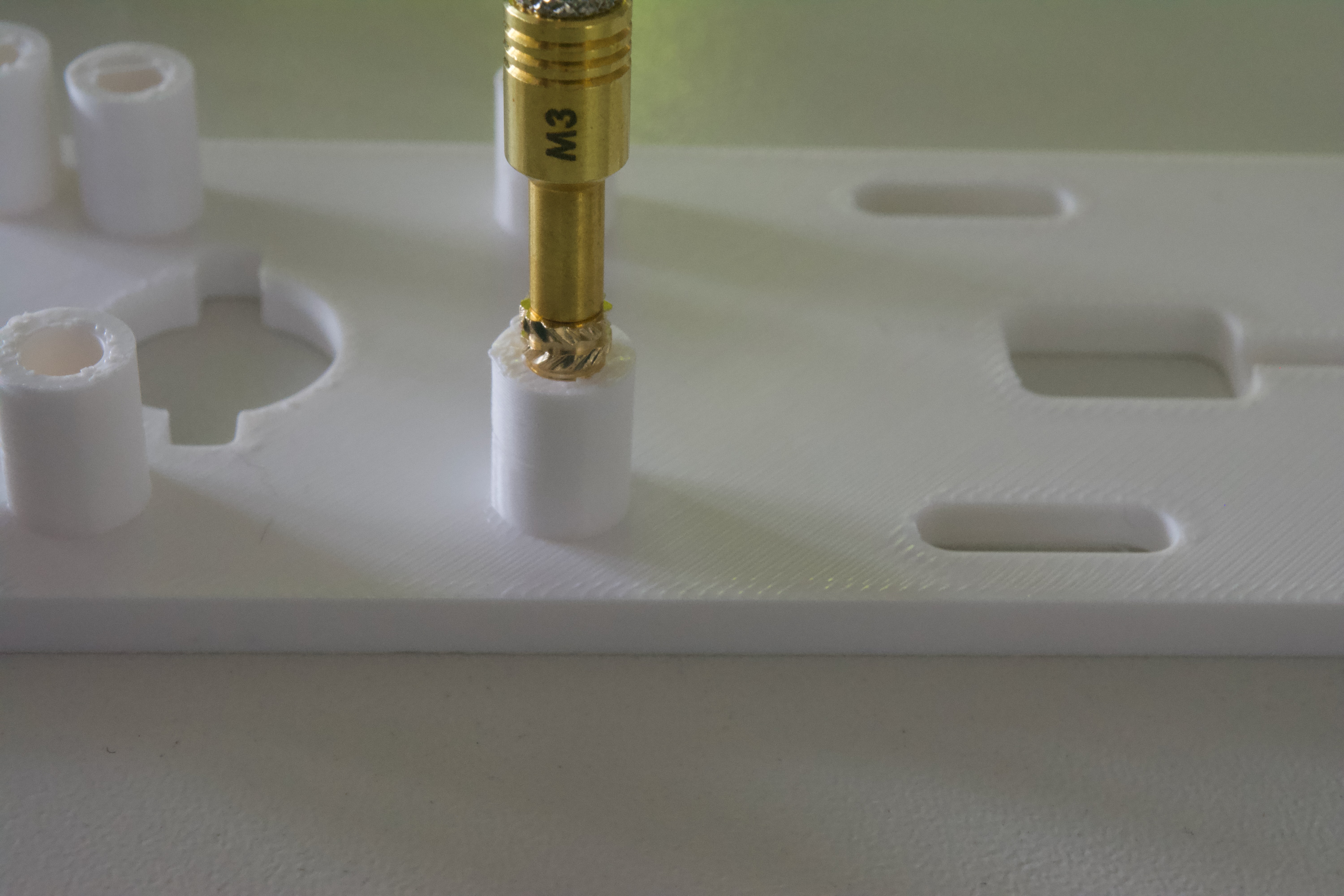
The ideal temperature for inserting the threaded inserts is around the melting point of the plastic or slightly higher. For PETG, I find that setting the soldering iron to approximately 245°C works well. Carefully push the insert into the plastic until it is flush with the surface, ensuring a secure fit.
The rest of the assembly process is straightforward, involving screwing the parts together, inserting the two bearings, placing the two magnets, press-fitting the Hall effect sensors, and connecting the cables. For accurate placement, please consult the provided 3D model.
![]()