Electronics production
Our journey across different digital fabrication techniques continues with electronics production. Specifically, we focused on milling a PCB from a copper sheet. We were provided with schematics for an FT230X-based board that serves a dual purpose: it functions as a UPDI 3-pin programmer and, when used in USB to serial converter mode, it offers similar functionality to an FTDI cable. In UPDI mode, it can be used to program a UPDI target using serial communication.
We utilized KiCAD for the board design. To generate the files necessary for milling the board on the CNC, we had to open the project files in KiCAD and navigate to File > Plot.
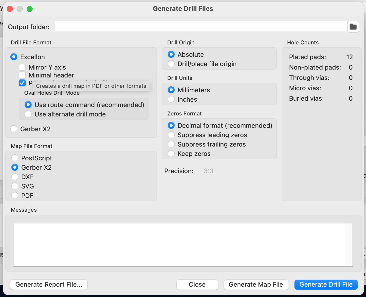
First, generate the drill files with the following settings:
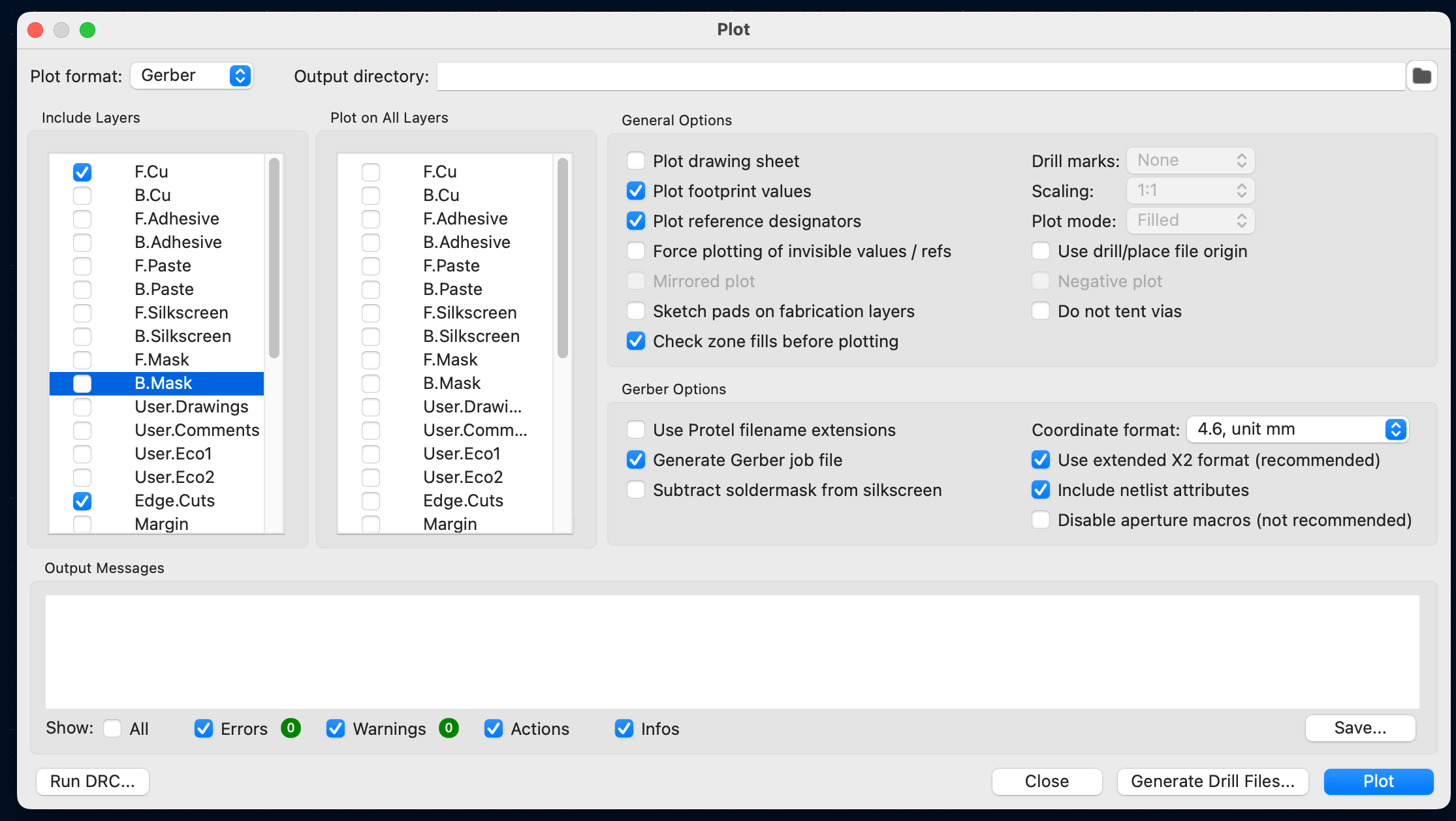
Then, plot the remaining layers, using only the F.Cu and Edge.Cuts layers:
With these steps, we have all three files needed to manufacture our board.
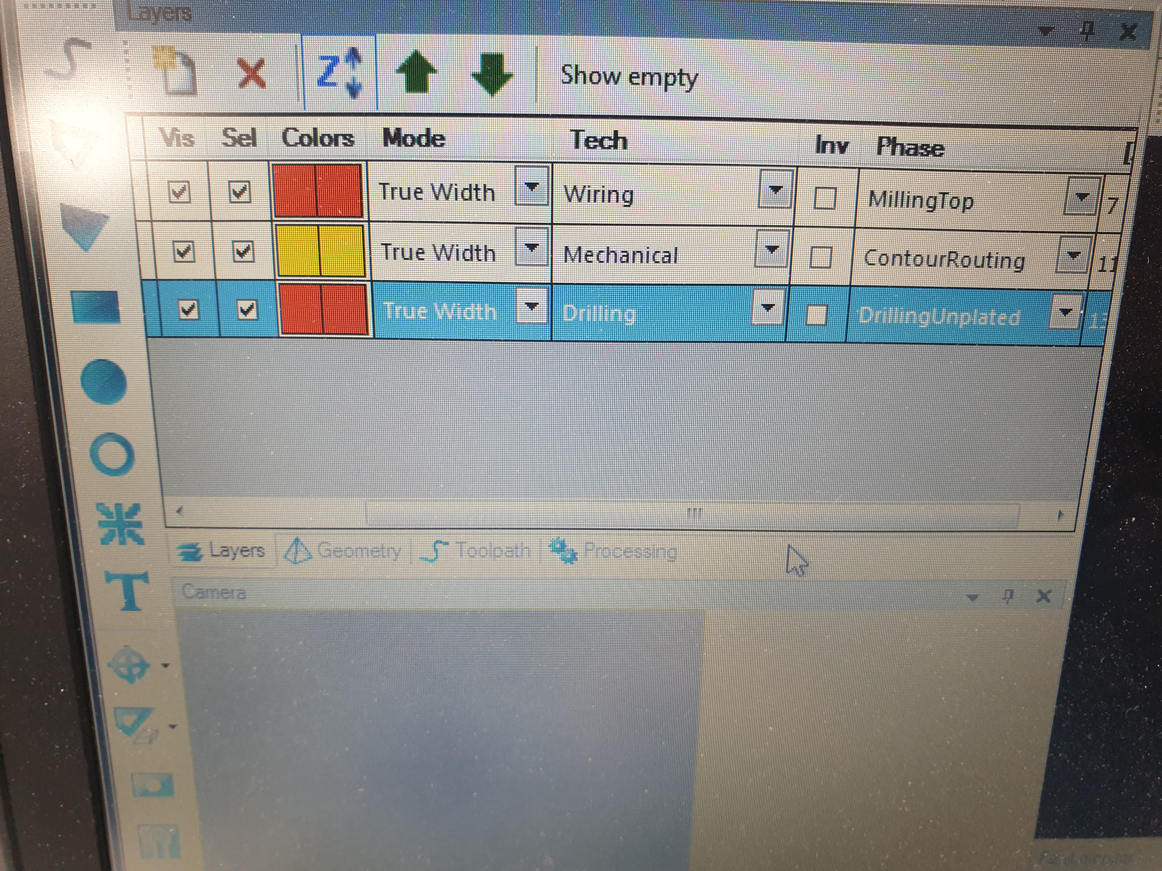
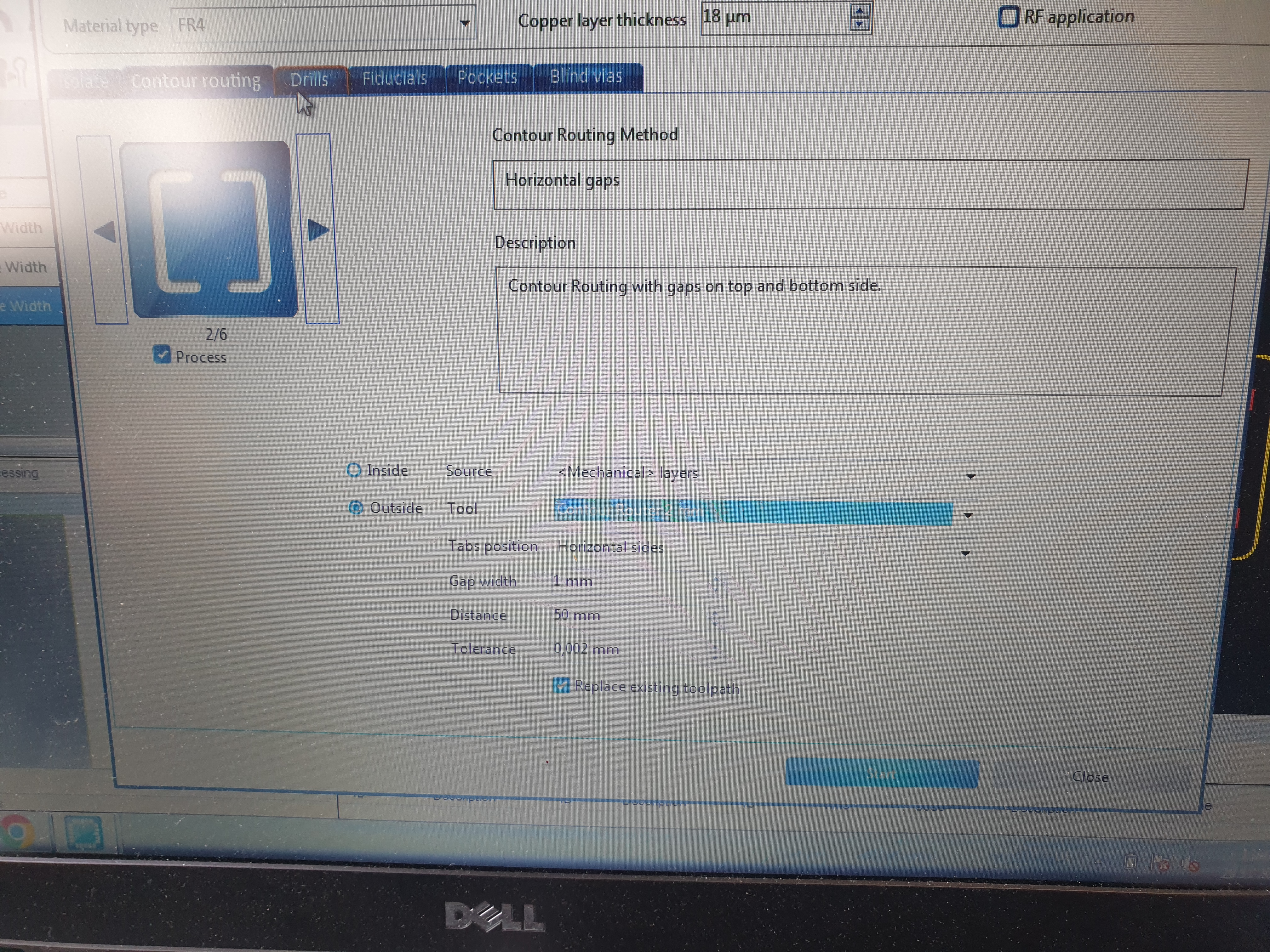
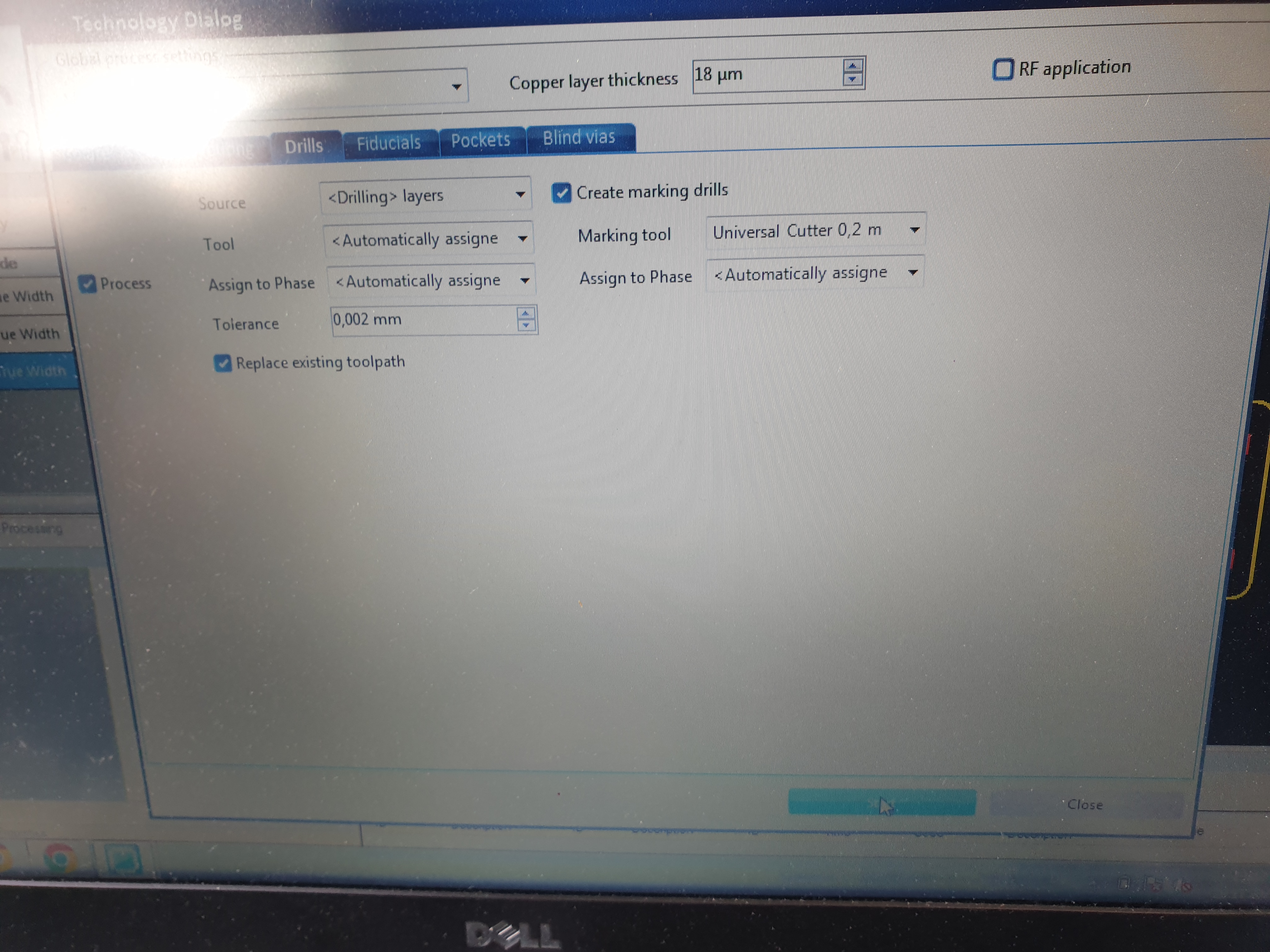
After importing the files into the CNC software, some settings required adjustments:
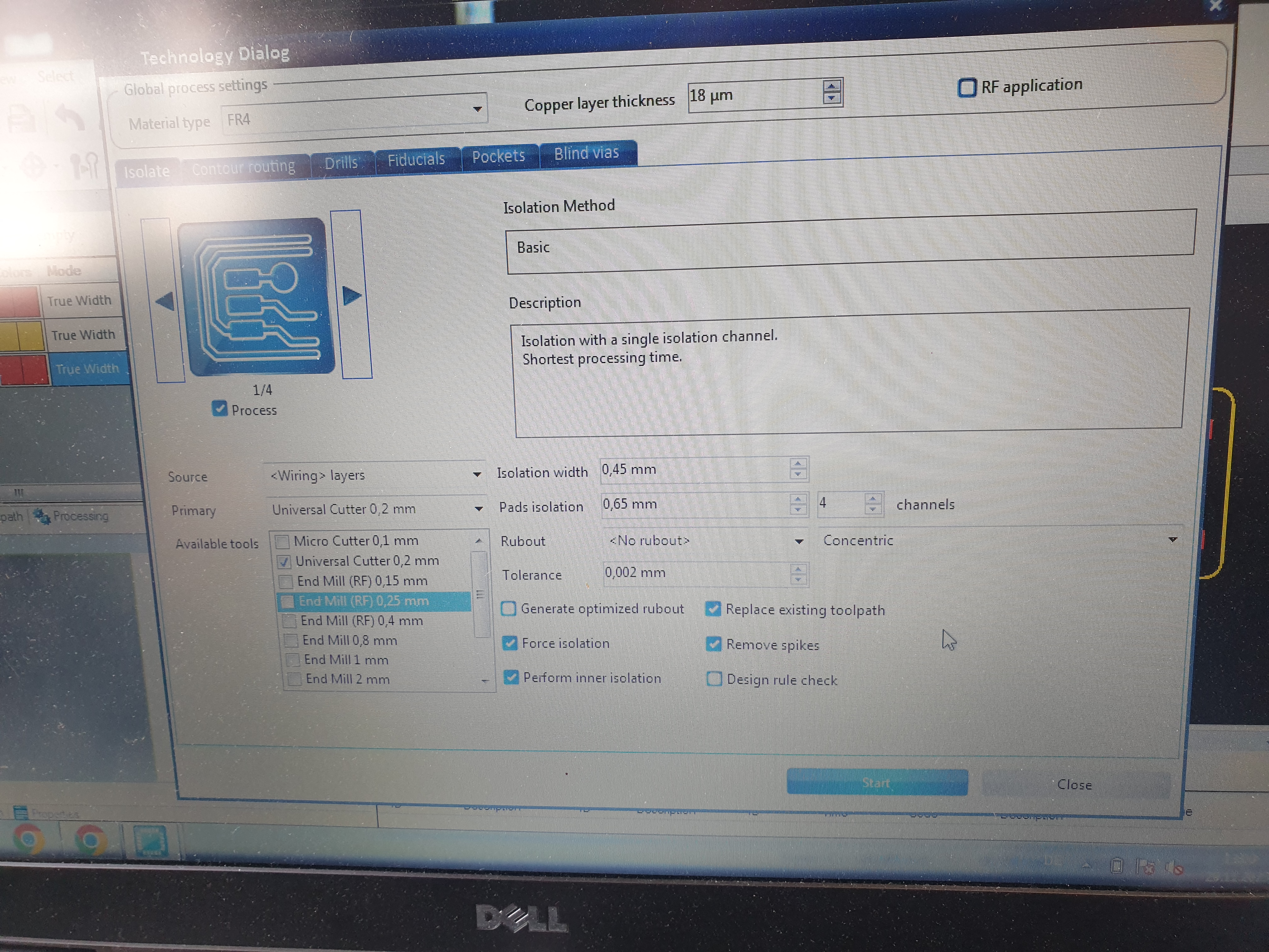
Upon accessing the "Technology Dialog," also change the following settings:
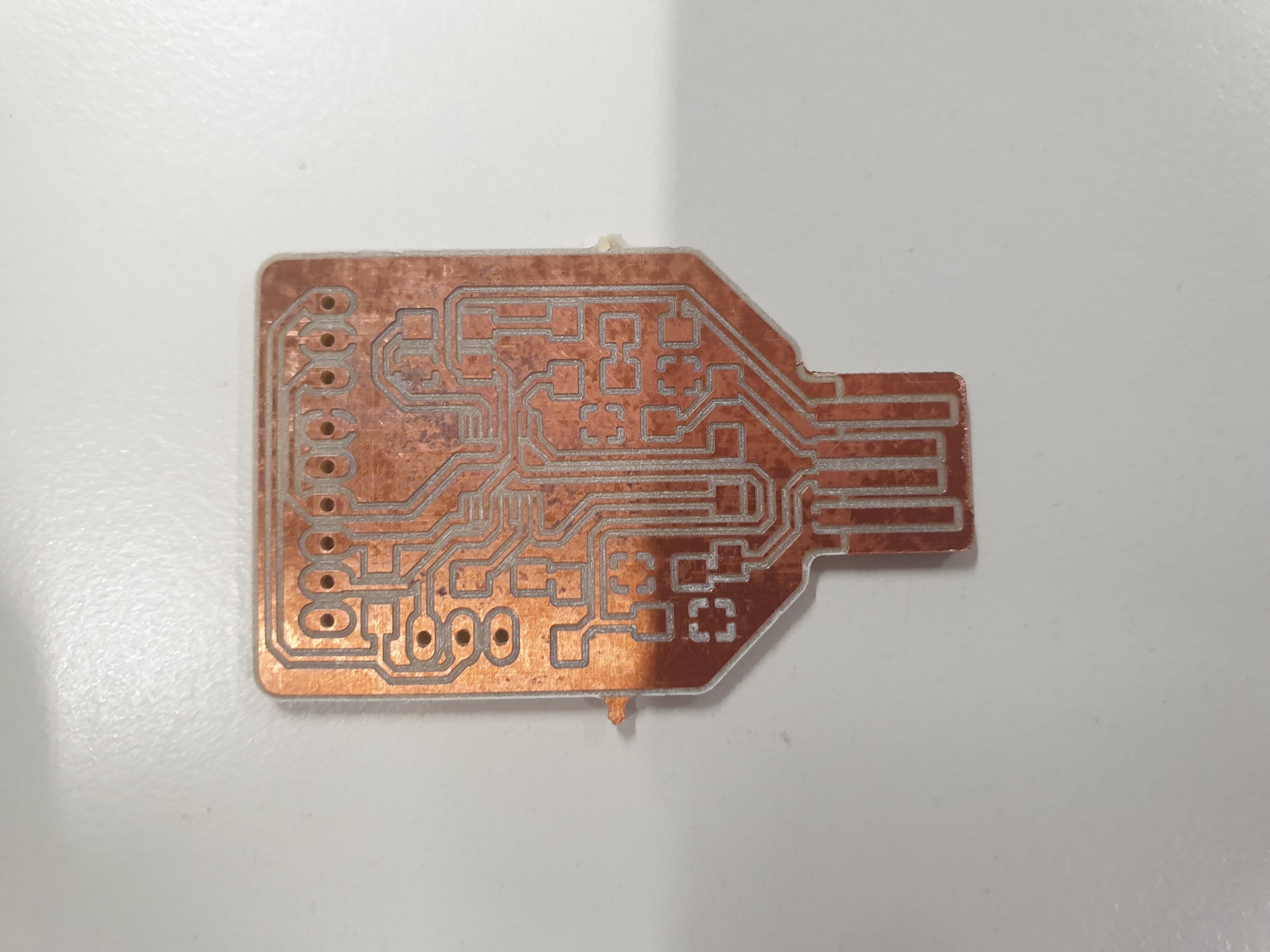
Next, we opened the "Board Production Wizard" and followed the steps, which were quite intuitive.
The finished result looks like this:
The final step involved soldering all the components provided in the Bill of Materials (BOM) onto the boards. All components, except for the pins, were surface-mounted. This was by far the most time consuming and complicated step.
This is what the finished board looks like:
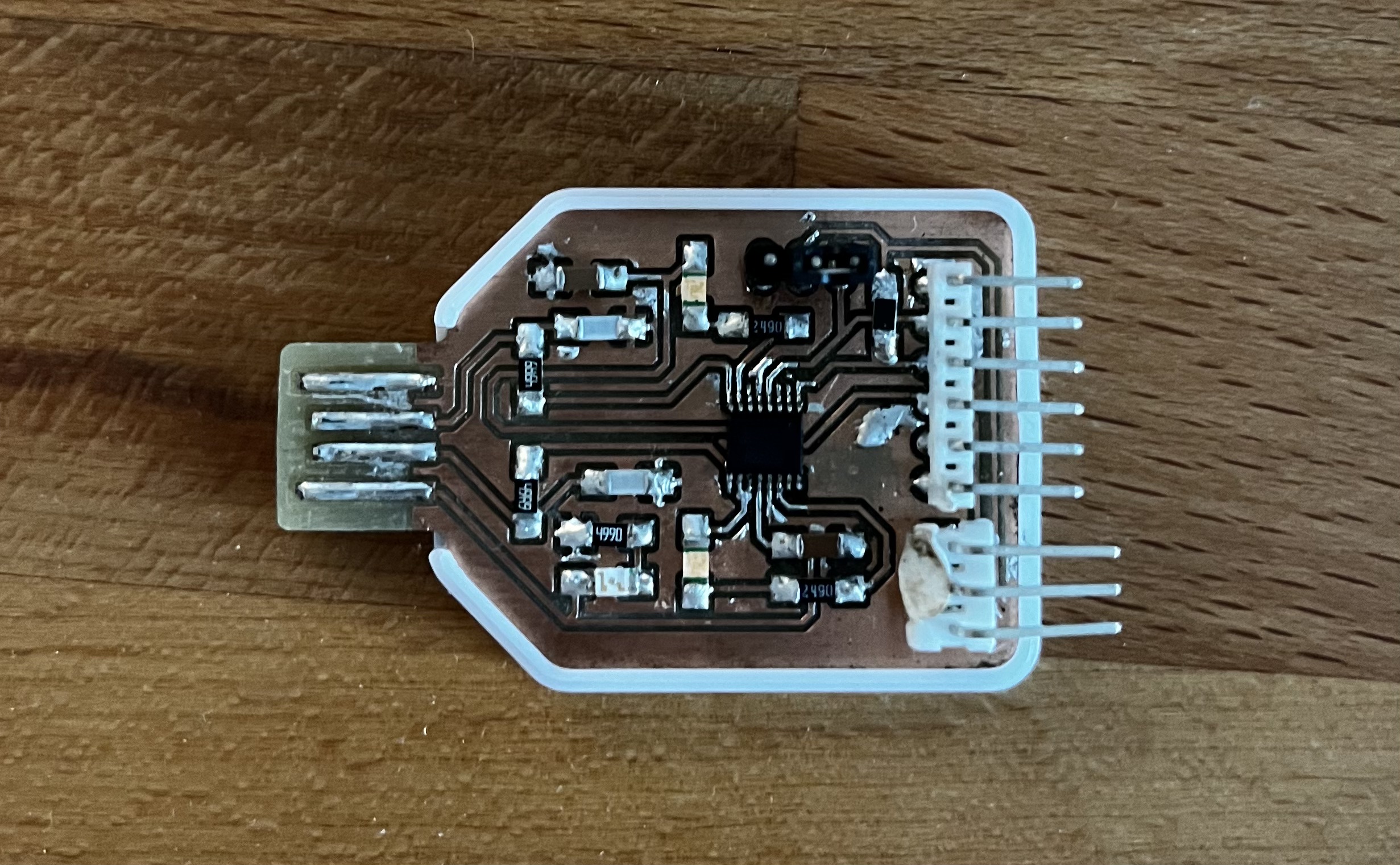
After soldering everything together the only step left was to check for any shorts and test the boards functionality.